Repairing a junk amplifier
While wandering around a junk store, I found an amplifier I wanted (DENON PMA-390) for sale at a reasonable price.
It was made in the late 1990s.
The reason for the junk was that “no sound came out from one side (L-channel)“.
I decided that the failure case of no sound from one side would be a good deal because it could be repaired immediately! I decided to purchase it.
(As I will explain later, I suffered quite a bit later because of my careless mistake…)
This would be super profitable if it could be repaired!
It’s a purchase. This is a purchase!
Here’s a junk amp that I bought at a very reasonable price.
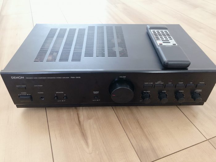
Beautiful item with remote control and almost no scratches on the exterior. A good buy (as long as it plays sound).
So, I will explain how to repair a failed junk amplifier.
Depending on the symptoms of the malfunction, which parts should be suspected as the suspect parts! and how to repair the suspect parts.
Let’s buy a junk amp that has broken down, revive it, and make it sound good.
How to Repair a Failed Amplifier (High Road)
The factors listed below account for the majority of amplifier failures.
For example, relays, volume (variable resistors), and electrolytic capacitors are the most common components because their failure is inevitable after long use.
Therefore, in many cases, amplifier failures can be repaired by yourself if you keep the points in mind. When you discover a treasure at a junk shop, one of the criteria for deciding, “Can this be fixed?” It may be beneficial to know this information as one of the criteria for judging whether an amplifier can be repaired or not.
The following are the six most common cases of amplifier failure, and the younger the number, the higher the probability of occurrence.
1. Poor contact of cable terminals
| condition | – Sound does not come out from one side. – Intermittent sound or no sound. |
| how to identify | Shake the speaker cable or RCA cable and try to find out if there is any rustling or change in sound. If there is a rustling sound, it is often due to poor contact with the terminals. |
| how to fix | Spray the terminals with contact revivifier and clean the contacts with a cotton swab or similar tool. Or, retighten loose speaker terminal screws. |
2. Relay failure
| condition | – No sound from both sides. – No sound from one side. – The sound from one side is extremely muffled. – Sound does not come out from one side, but it may be temporarily fixed by increasing the volume. |
| how to identify | – Fundamentally, it is good (but a little difficult) to check if the relay is working properly by looking at the waveforms of the signals before and after the relay components with an oscilloscope. – For simplicity, try popping the relay case with your finger and see if it improves temporarily. |
| how to fix | – Temporary remedy: Remove the relay case (cover) and remove dirt from the relay contacts inside with contact revivifier and a file. (If there are no parts around the relay, it may be possible to repair the relay without using solder, but if the relay cover cannot be easily removed, it may be necessary to use solder to remove the relay) – Root remedy: Replace the relay parts (about $5) |
3. Volume failure
| condition | – Noise is generated when the volume is turned. – Sound does not come out. – Sound comes out even when the volume is turned to the minimum. |
| how to identify | – Turn the volume control to see if there is any strange behavior such as noise generation. |
| how to fix | – Tentative solution 1: Spray contact revivifier through the gap in the volume and turn the volume several times to remove defective contacts. – Tentative remedy 2: Disassemble the volume and clean it (very effective, but soldering work is required). – Root remedy: Replace the volume parts (if the volume is linked to the remote control, it is often difficult to do this because there may be no compatible parts). |
4. Failure of balance VR (variable resistor)
| condition | – No sound from one side. – When tone control is turned on, no sound comes out from one side. |
| how to identify | – Turn the left/right balance volume and see if there is a temporary improvement. – If the balance VR is half dead, turning the volume may cause the sound to become louder or quieter or behave unstably. |
| how to fix | – Tentative solution 1: Spray contact revivifier through the gap in the balance VR, and turn the volume several times to remove defective contacts. – Tentative solution 2: Disassemble the balance VR and clean it (very effective, but soldering work is required). – Root remedy: Replace the balance VR parts (sometimes difficult because there may be no compatible parts). |
5. Electrolytic capacitor failure
| condition | – No power. – Sound does not come out. – Sound loses sharpness. – Noise in the sound |
| how to identify | – Visually check for bulging or leaking electrolytic capacitors. |
| how to fix | – Replace electrolytic capacitor (soldering work required) |
6. Cracked solder
| condition | – No sound on one side. – No sound coming out of one side. |
| how to identify | – Check for cracks in the solder by visually inspecting the soldered parts of the board. – Play the parts with your fingernail to check for any change in sound. |
| how to fix | – Re-soldering |
Practical instruction (PMA-390II repairing)
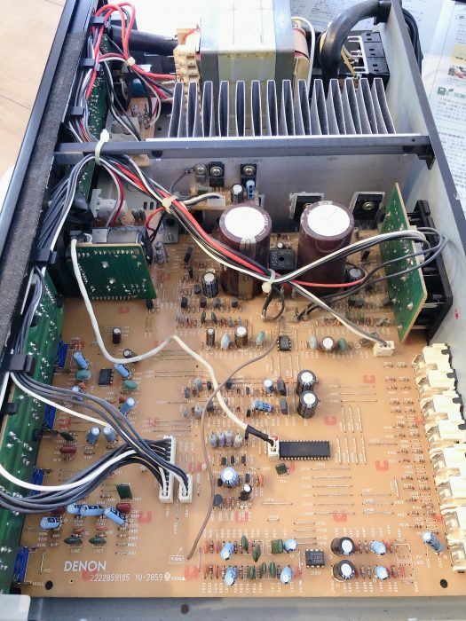
First, I opened the case and checked if there was anything “obviously wrong,” such as blown electrolytic capacitors or burnt parts.
There seems to be no problem.
Relay contact failure improvement
Based on the symptom of no sound coming from one side (no sound from L-ch), I decided that it was most likely a bad contact with the relay, so I decided to disassemble and repair the relay next.
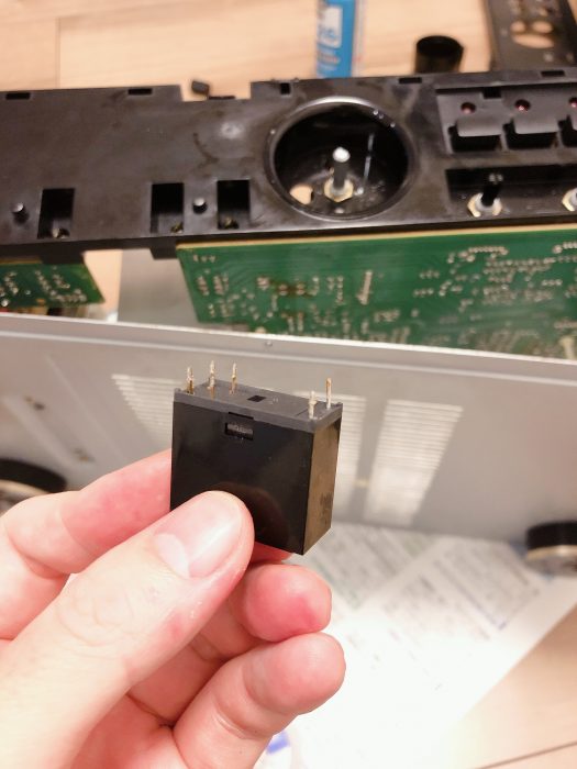
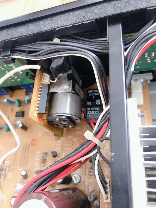
The relay is a 24V DEC relay called DH2TU. This relay is quite commonly used.
The relay cover could not be removed without first removing the relay from the printed circuit board, since the volume and coils are located on both sides of the relay.
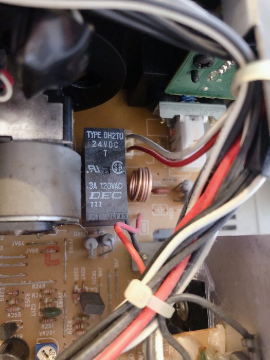
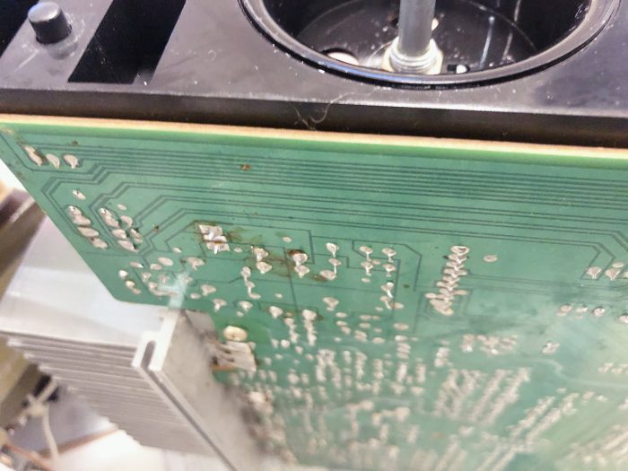
When I looked at the soldering area of this relay, there was burnt flux that looked like it had been re-soldered.
It appears that the previous owner had repaired the relay.
Using a soldering iron and desoldering wire, suck out the solder from the relay and remove the relay components.
If you have a solder sucker, it is more useful to suck out the solder.
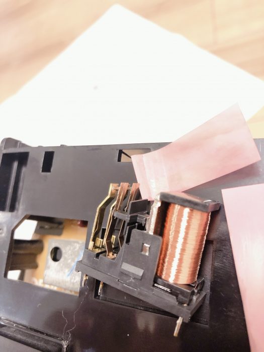
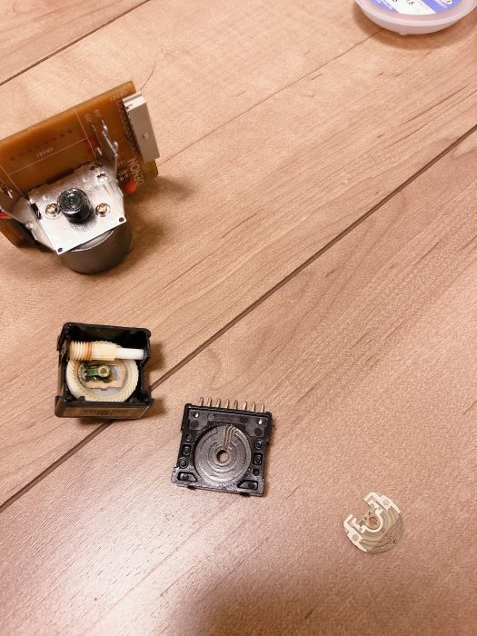
This is the removed relay.
Insert a flat-blade screwdriver or similar tool into this cover and remove the cover.
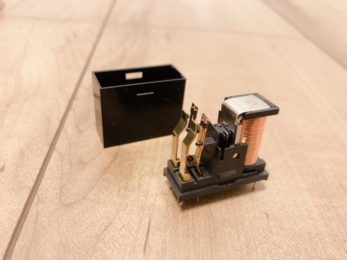
The way the relay works is that when voltage is applied to this coil, a magnetic field is generated, and the middle terminal repels and moves to contact the terminal at the end, turning it ON.
If this terminal gets dirty, a bad contact occurs.
My relay had black terminals (although rumor has it that some relays have carbon powder on them to improve contact, so they may have been black to begin with).
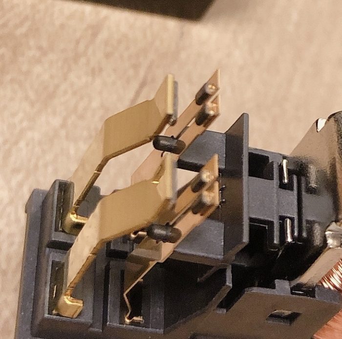
I tried spraying contact revivifier and rubbing with a cotton swab, but it did not improve, so I decided to polish it with a file.
Fine grit waterproof paper is good.
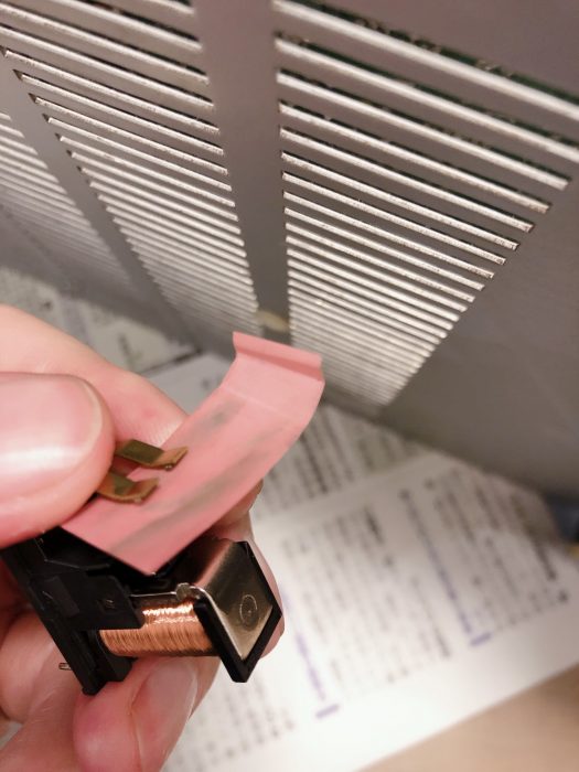
Polishing with water-resistant paper gave it such a shiny golden color. The finish should be lightly sprayed with contact revivifier to prevent rusting.
I cleaned the relay so far, but the failure did not improve. It was so black, but it wasn’t a relay failure! Why!?
Improving volume contact points
Next, I suspect the volume (it doesn’t seem to be a volume problem in particular, but when in doubt, punish).
The PMA-390II’s volume is linked to a remote control, and the volume rotates mechanically, a method that was common in slightly older amplifiers.
Since there are no gaps or holes in this volume to pour contact revivifier, I decided to disassemble it.
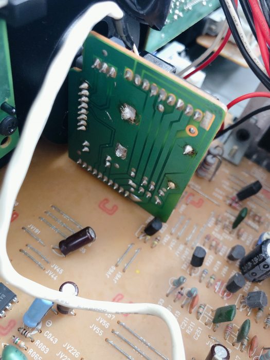
The volume was composed of an independent board, connected by a connector, so we first removed this independent board.
It is a volume made by Alps with the model number 2110857002.
Alps is a vendor of volume (VR: variable resistor) and is famous for its high quality (and therefore high price).
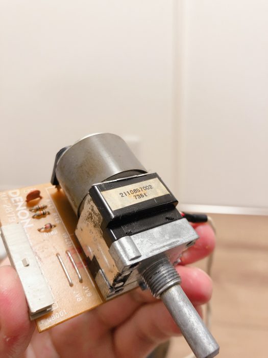
Remove the clasp by bending the metal claw that holds the front half of the part with a flat-blade screwdriver or similar tool.
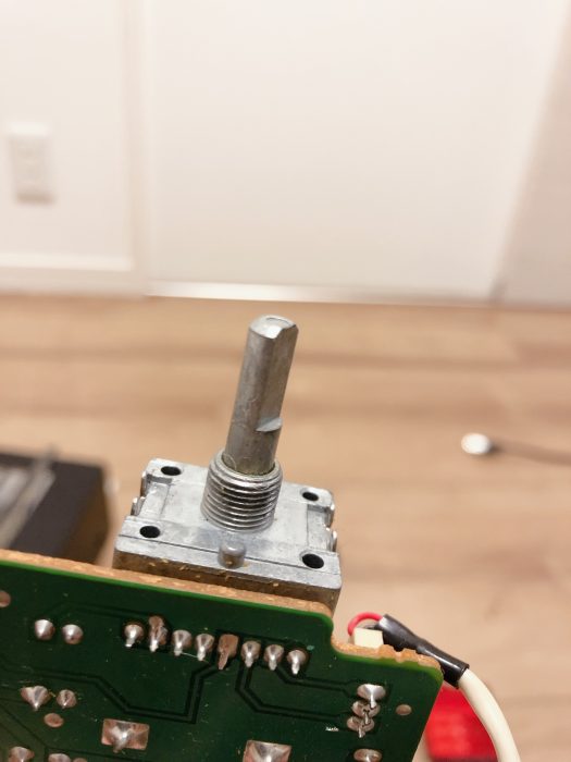
I could remove the stick part first like this.
Disassembly of the blue part seemed to be impossible without sucking out the solder, so I decided to suck out the solder.
(However, my soldering iron is a 15W soldering iron for precision parts, which does not get very hot, so I could not melt the solder on the metal fixing part of the volume connected to the GND)
Thus, I decided to suck out the solder of this 8 pin connector and remove only the first half of the part.
Melt the solder, float and remove the blue part of the first half.
I am almost done to the contact point!
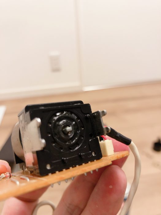
The volume could be easily disassembled like this.
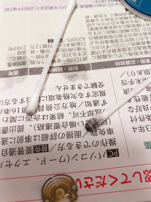
Sprayed with contact revivifier and cleaned with a cotton swab.
It seemed to be dirty, and the cotton swab became so black.
Cleaning the volume did not solve the problem of no sound from one side (L-ch).
(That’s because it’s not a symptom of volume failure. But it did prove that the volume was not the culprit.)
Improving contact points for balanced VR
As a symptom of sound not coming out of one channel, the balance VR (variable resistor) is quite often the suspect.
In particular, wandering through the web articles, I found that the PMA-390 has many failures due to poor contact points of the balance VR.
That is why I decided to improve the contact point of the balance VR.
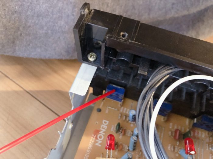
This blue VR is the suspect balance VR.
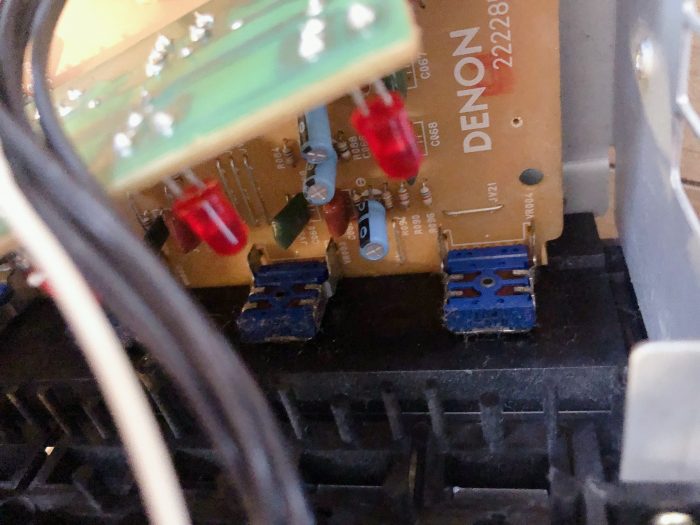
There is a hole in it, so you can do a first aid treatment by spraying contact resurrector from here, but I decided to punish it more directly, so I disassembled it.
(The following figure shows the LOUDNESS VR, not the balanced VR. The fourth from the left is the balance VR)
Due to the insufficient heat of the soldering iron (15W is not enough), I could not melt the solder of the metal part fixing the balance VR, so I decided to melt the solder of the pin part only and float only the blue plastic part to disassemble it.
The VR is called 104MN, but I couldn’t find it in my search on google. If I break this one, I can’t get a replacement, so I have to be careful (I said so, but I pulled it off with all my might).
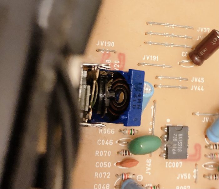
In this condition, I could see the contacts, so I cleaned them with contact revivifier and a cotton swab. Again, the cotton swab turned black.
I was quite hopeful that this might improve the sound. I tried to play sound, but there was still no sound from one of the channels.
I convinced myself that this was just routine maintenance, since the relay and VR would eventually break down if not maintained since the amp was 20 years old.
Identifying the faulty part in earnest.
I had no choice but to use an oscilloscope to identify the faulty part (I should have done this from the beginning, but the oscilloscope is stored in the storage room on the rooftop, and it is a hassle to go get it. Well, it’s more trouble to disassemble the VR).
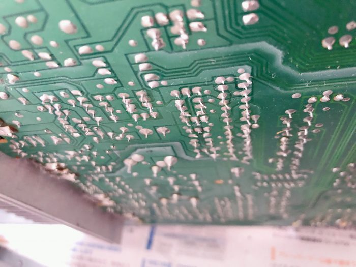
Before that, I checked the circuit board for solder cracks, and confirmed that there seemed to be no problem.
Now comes the oscilloscope.
A proper oscilloscope is expensive, usually costing more than $500, but recently, a simple oscilloscope made in China is available for about $40. It is a very convenient time. If you are a DIY audio hobbyist, you should have one oscilloscope.
Put music into the input and look at the waveform on the oscilloscope like this.
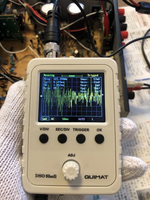
If you set the time axis to about 50ms and look at a range of 5mV to 0.1V AC, you can see something like the sound waveform of DJ software.
The dynamic range of the voltage depends on the volume of the amplifier, so you would change it accordingly.
(I think it was like observing the input signal at about 5mV to 20mV and the output of the amplifier at about 0.1V)
When working with the amplifier powered on, you should absolutely take the following precautions
– Do not disassemble the case or make any other configuration changes when the power cable is inserted.
– Wear insulated gloves (or at worst, military gloves) when working on the amplifier.
– Always be aware of the possibility of electric shock (do not do anything reckless).
Check the waveforms with an oscilloscope.
- RCA jacks used for music input from iPhone -> Signal present on both left and right
- Signal line in front of speaker protection relay -> Signal present on both left and right
- Signal line at the output of the speaker protection relay -> Signal present on both left and right
- Base of speaker terminals -> Signal present on both left and right sides
What the hell is that? Where are you losing the L-channel signal?”
I’ve got sound signals coming in both left and right to the speaker terminals.
Where is it lost?
So, I fixed the loose screws on the speaker terminals and tightened them up…
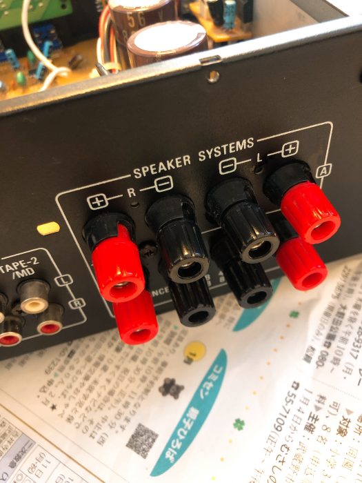
Both left and right sides sounded fine, as if nothing had happened!
What a blind spot.
I had read at the junk shop that “no sound comes out from L-channel,” so I took apart the relay, volume, and even the balance VR, but I had no idea that it was caused by such an elementary thing.
Anyway, I am glad it sounded good.
about PMA-390II amplifier
The PMA-390, despite its inexpensive price range, is a model that is quite highly regarded for its high sound quality because it uses audio grade components and is excellently designed (among DENON’s audio series, only the 390 series is said to have a different designer).
The first generation PMA-390 used a toroidal transformer, and I heard that people were talking about it, saying, “A toroidal transformer is used for this inexpensive price!”
Unfortunately, after the second generation PMA-390II, the toroidal transformer was discontinued and a regular transformer power supply was used. I am planning to convert this transformer power supply to a toroidal transformer to improve the sound quality in the future.
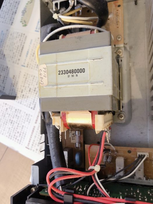
Transformer power supply for PMA-390II 2330480000
On the other side of the degreasing of the transformer power supply, the second and later generations can be operated with a remote control.
Although I preferred the first generation PMA-390 in terms of sound quality, I had my sights set on the second and later generations of PMA-390s because the remote control is a must.
Unlike subsequent generations of PMA-390III, PMA-390IV, PMA-390AE, PMA-390SE, and PMA-390RE, the PMA-390II has push-button input switching instead of a rotary volume switch.
The rotary volume is another component that is prone to failure, so we chose the push-button PMA-390II (partly because it was cheaper).
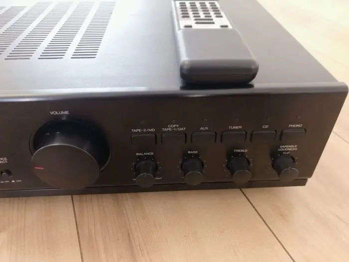
It has a very simple appearance.
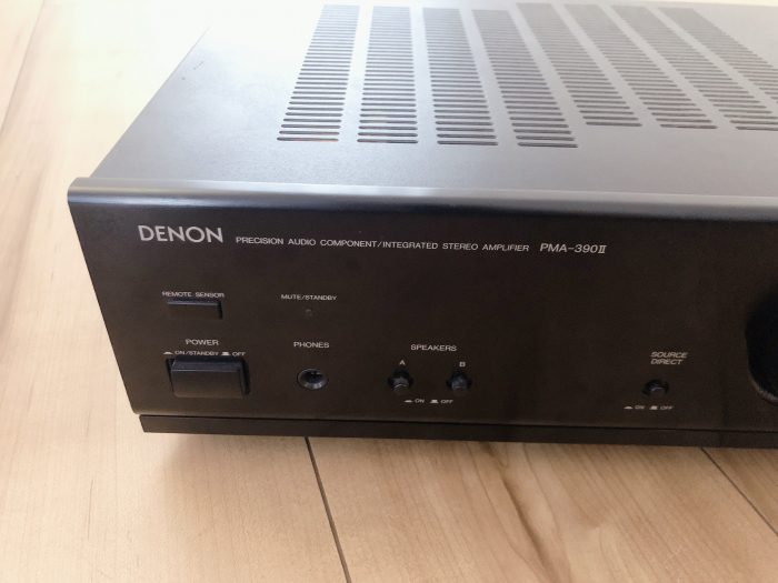
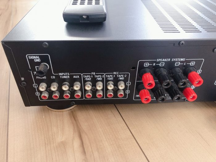
There are three inputs in addition to the PHONO for input from records.
Two speaker outputs are available, and the outputs can be switched by a switch.
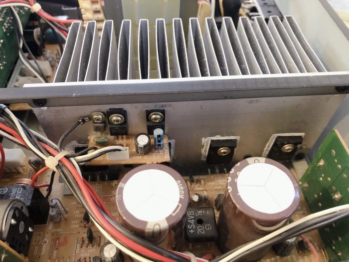
Two 8200uF / 56V audio electrolytic capacitors were used in the PMA-390II as smoothing capacitors for smoothing the AC to DC power supply.
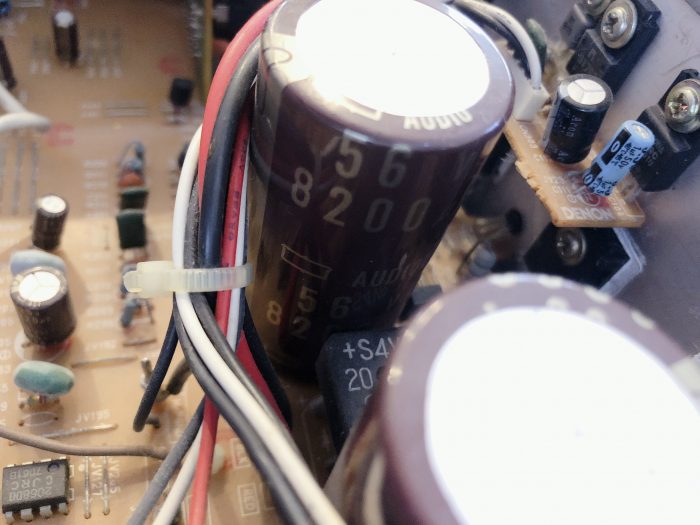
Since it is 20 years old, its capacity will have decreased, so this is one of the parts we would like to replace in the future.
The central part of the amplifier is made of discrete circuits using transistors, not ICs.
It is a fairly simple circuit and seems to be easy to maintain.
The electrolytic capacitors around this amplifier circuit should also be replaced.
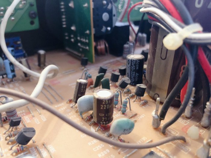
An op-amp is used for the PHONO input and tone control circuitry, and it is JRC’s 2068DD.
This op-amp is highly regarded for its low distortion, high sound quality, and versatility.
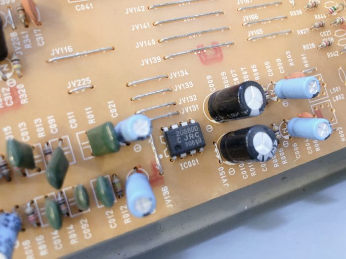
A total of four transistors, two 2SC4278 and two 2SA1633, are used at the heart of the amplifier.
2SC4278: manufactured by ROHM, 150V npn transistor
2SA1633: manufactured by ROHM, 150V pnp transistor
There are some enthusiast websites that compare the sound quality of different transistors, but I could not find any information on the sound quality of these transistor ICs. This transistor IC seems to be available for about $3 if you look for it.
As a trivia, the first three letters of transistor have the following meanings. “2S” stands for two Semiconductors.
- 2SA:High-frequency transistor with PNP junction
- 2SB:Low frequency transistor with PNP junction
- 2SC:High-frequency transistor with NPN junction
- 2SD:Low frequency transistor with NPN junction
A rather large heat sink is used to dissipate the heat generated by these transistors. The heat sink dissipates the heat generated by these transistors and the regulator IC.
The power transformer and regulators occupy the left half of the panel, and the heat seems to have been prevented from going to the signal line components as much as possible.
In the future, I would like to try to improve the sound quality by replacing the electrolytic capacitors. I am looking forward to it.
Comments