Introduction
I heard that it is easy to make a power amplifier using an IC called TA2020-20.
Since I wanted an amplifier, I decided to try making one.
I like reggae music, so I want to make a nice amp with louder bass that goes well with reggae music.
I heard that there is a DIY kit out there that uses TA2020.
And it is said that by replacing the capacitors and coils in the kit, it is possible to achieve even higher sound quality.
Considering that I would have to replace capacitors and other components later, I did not purchase a kit, thinking that it would be cheaper to build a circuit on a universal board using great components from the beginning without using a kit.
Since I have next to no knowledge of audio, I borrowed the wisdom of my predecessors in purchasing components by typing “TA2020 bass” and “TA2020 capacitor” into Google.
Parts collecting
Amplifier
| Parts | Model No. (Manufacturer) | Price | |
|---|---|---|---|
| #1 | digital amp IC | TA2020-20(Tripath) | $15 |
| #2 | Schottky diode for rectification x 8 | 1S4 41V 1A | $0.2×8 |
| #3 | Resistance (10 ohms) x 2 | 1/2W metal film plate 1% *(Nikkohm) | $0.3×2 |
| #4 | Resistance (20 k ohms) x 4 | 1/2W metal film plate 1% *(Nikkohm) | $0.35×4 |
| #5 | Resistance (8.2 k ohms) | 1/2W metal film plate 1% | $0.3 |
| #6 | Capacitor (0.01micro F) x 2 | MKT1826 Metallized polyester film capacitor (ERO) | $1×2 |
| #7 | Capacitor (0.1micro F) x 8 | MMD2E104N Metallized polyester film capacitor (Nittsuko) | $0.3×8 |
| #8 | Capacitor (0.22 micro F) x 2 | MKT1826 Metallized polyester film capacitor (ERO) | $1.8×2 |
| #9 | Capacitor (0.33 micro F) x 4 | BG-PK electrolytic capacitor (Black Gate) | $0.25×4 |
| #10 | Capacitor (1 micro F) x 2 | MMD2E105N Metallized polyester film capacitor (Nittsuko) | $0.3×2 |
| #11 | Capacitor (2.2 micro F) x 2 | BG-C 50WV Pure low noise coupling electrolytic capacitor (Black Gate) | $0.8×2 |
| #12 | Capacitor (3300 micro F) × 4 | KMG 105℃ (Japan Chemi Con) | $1 |
| #13 | Coil (10 micro H) x 4 | TA2020KIT-SP Coil with attached magnetically shielded case | $8 |
| #14 | universal infrastructure | Single-sided glass epoxy 72 x 47 mm | $0.5 |
| #15 | Distribution cables | SONY mini-component DHC-MD333 with attached speaker cable | – |
#1 TA2020-20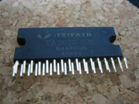 This digital amplifier IC from Tripath is an environmentally friendly amp with an amazing 85% high efficiency (at 6 ohms for speakers). The power amp is 20W+20W, which is more than enough power to connect to 2-way speakers of a mini-component. The sound is said to be very good, so I am looking forward to using it. | #2 1S4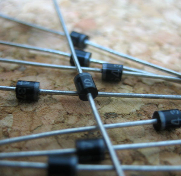 Schottky diode for rectification. Withstand voltage 40V, 1A, rise voltage VF = approx. 0.4 to 0.5 V. Since it is for clipping to prevent OUTPUT voltage from going below GND and above VDD, I chose one with low rise voltage VF. | #3 Nikkom 10 ohm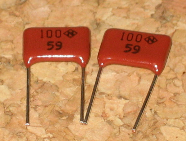 A resistor that forms a Zobel network, which is explained in an easy-to-understand manner on the website of speaker-related technical materials. I used a plate resistor, although an ordinary metal film resistor would have been fine. Plate resistors are also metal film, but they are said to have a sound somewhere between metal film and carbon resistors. |
#4 Nikkom 20 k ohm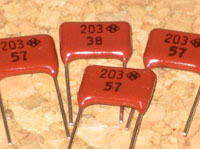 The resistors are used to determine the gain of the feedback circuit. Since these resistors are in series with the signal, they seem to be largely responsible for the sound. I will use a plate resistor here as well. | #5 Metal film resistance 8.2 k ohm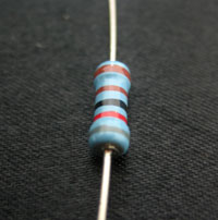 It seems to be a bias resistor. Why only this part was made to have a metal film is a mystery to the author. Actually, no, I forgot to buy a Nikkom’s plate capacitor. | #6 MKT1826 0.01 micro F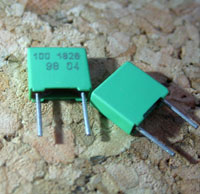 ERO’s metallide polyester film capacitor for audio use, connected to the OUTPUT as a parallel to remove high-frequency components of noise coming from the speakers (to?). It is said to be called “Differential Output Capacitor” but I don’t know the details. |
#7 MMD2E104N 0.1 micro F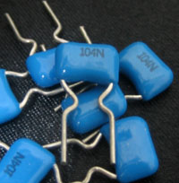 Used for the pass-controller. Since 8 film capacitors are used in total, I chose the cheapest possible film capacitors. I don’t know what kind of sound it will make, but I think it will be good sounding because it is an audio-use metallide polyester film capacitor. (Incidentally, I heard that ceramic capacitors are better suited for passcons than film capacitors, but that’s okay at this point.) | #8 MKT1826 0.22 micro F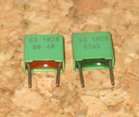 The capacitors that form the Zobel network, ERO’s audio metallide polyester film capacitors. This series is said to have a reputation for sounding quite good. | #9 BG-PK 0.33 micro F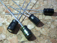 Output capacitor. It is said that it is good to change the capacitance according to the impedance of the speaker. (To get impedance matching?). According to the data sheet of Tripath, the following values are recommended. 4Ω: 0.47 micro F 8Ω: 0.22 micro F My speakers have 6 ohms, so I guess I should use 0.33 micro F capacitors. Since I like bass, I decided to use Black Gate, which is notorious for its bass sound. |
#10 MMD2E105N 1 micro F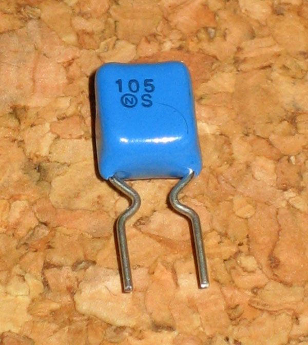 A decoupling capacitor attached to the output of a charge pump. It is said that this charge pump produces a very small amount of voltage above VDD, but I have no idea why a charge pump is necessary here. For now, I will use audio metallide polyester film capacitors, which I could buy at a reasonable price. | #11 BG-C 2.2 micro F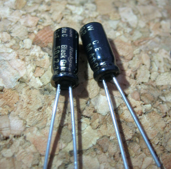 Input coupling capacitor. This capacitor is said to have a great influence on the sound. I tried to use Black Gate to make the bass sound more dynamic. This BLACK GATE is for ultra low noise coupling. | #12 KMG 3300 micro F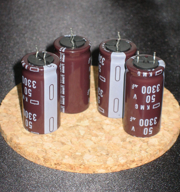 A condenser that I could buy for $1.00 for 4 bottles. The only reason why I chose these capacitors is because they were cheap. Since it is a power supply smoothing capacitor for ripple removal of switching power supply, I would have preferred a low impedance capacitor if possible… If I used all four capacitors, the capacitance would be 13200μF, which is too large, and I am afraid of inrush current, so I decided to use only three capacitors. |
#13 Coil 10 micro H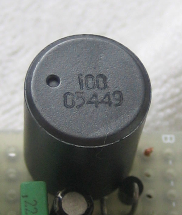 Coils in magnetically shielded case included with TA2020KIT-SP. I was going to make my own coil by winding enamel wire around a toroidal core, but reluctantly purchased it after realizing that I do not have the environment to measure inductance. Although the coils are in a magnetically shielded case, just to be safe, I tried to place them at intervals on the base so that the coils do not bond with each other as much as possible. | #14 universal infrastructure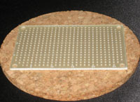 It is a single-sided glass epoxy, which is said to be resistant to breakage. It is also quite good looking. The size is small at 72 x 47 mm. I wonder if my prediction that this size would work is accurate. | #15 wiring cables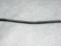 SONY mini-component DHC-MD333 speaker cable that comes with the DHC-MD333. It is a speaker cable, which is not bad for use in wiring. The thickness is probably 18 cores. |
Case, power supply, and wiring parts
| Parts | Model No. (Manufacturer) | Price | |
|---|---|---|---|
| #1 | switching AC adapter(12V、5A) | STD-1205 (GO FORWARD) | $15 |
| #2 | Power DC Jack | MJ-10 (Marushin Wireless Electric Co.) | $0.3 |
| #3 | Variable resistor (10kΩ 2-series A type) | RK27112 (Alps Mini Detent) | $17 |
| #4 | Toggle switch | MS-500K-B | $1 |
| #5 | Heat sink | 17P23L25 | $1 |
| #6 | Bracket LED (12V) | CTL701R | $1.5 |
| #7 | Knob | WT-37 | $2.5 |
| #8 | RCA plug x 2 | RJ-2008AT | $1×2 |
| #9 | Speaker terminal × 2 | BP-226G | $4×2 |
| #10 | Wiring cable | Speaker Cable 30 cores (2m) | $1.5 |
| #11 | Ferrite core | 5mm diameter type (TDK) | $1 |
| #12 | Case | UC9-5-12DD (Takachi) | $15 |
#1 switching AC adapter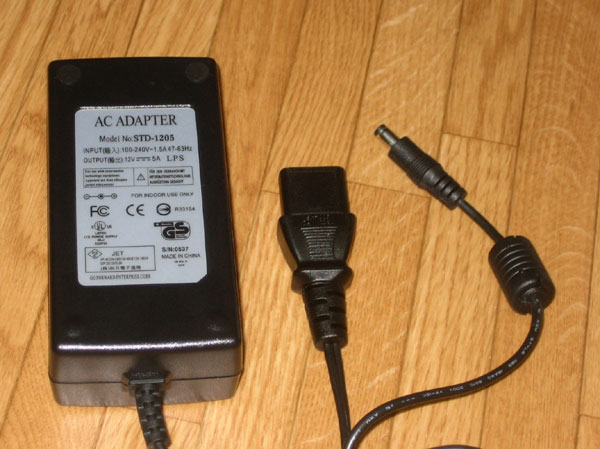 I was looking for a power supply with sufficient capacity for an amplifier with 20W+20W driving power, and found a 12V 5A switching AC adapter for sale at a reasonable price. I thought there must be something behind the price, but I did not care and used it. The output has a ferrite core. I think it will help to reduce the size of the amp and also help to reduce the noise emitted by the power supply. | #2 Power DC Jack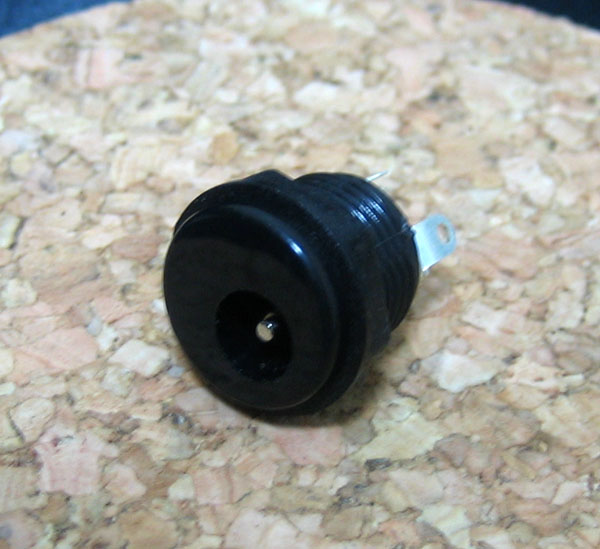 There are three terminals, and I am not sure which terminal is positive and which is negative, but I will install them in the case as appropriate. I’d like to use a tester to identify them, but I’m afraid the tester’s fuse might blow (the voltmeter has a large input impedance, so I’m not sure if it was safe…). | #3 Variable resistor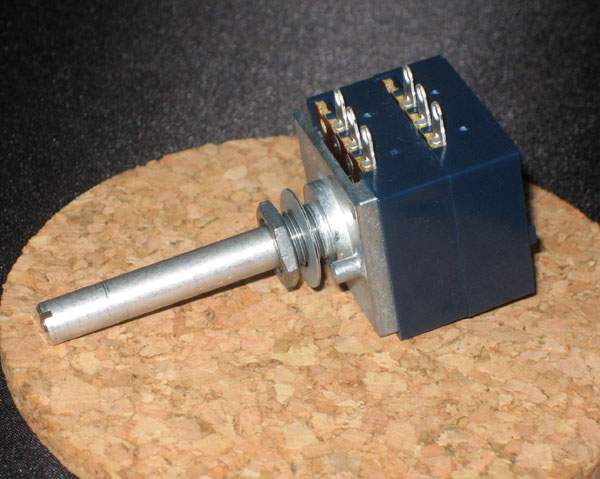 Alps mini-detent with a reputation for sound quality. It is very expensive, but I heard that we shouldn’t be stingy here. I spent my allowance to buy it in order to have a great sounding amp. When I turned the shaft, I was happy to feel a click and a sense of quality. The shaft is too long and has to be cut with a hacksaw. |
#4 Toggle switch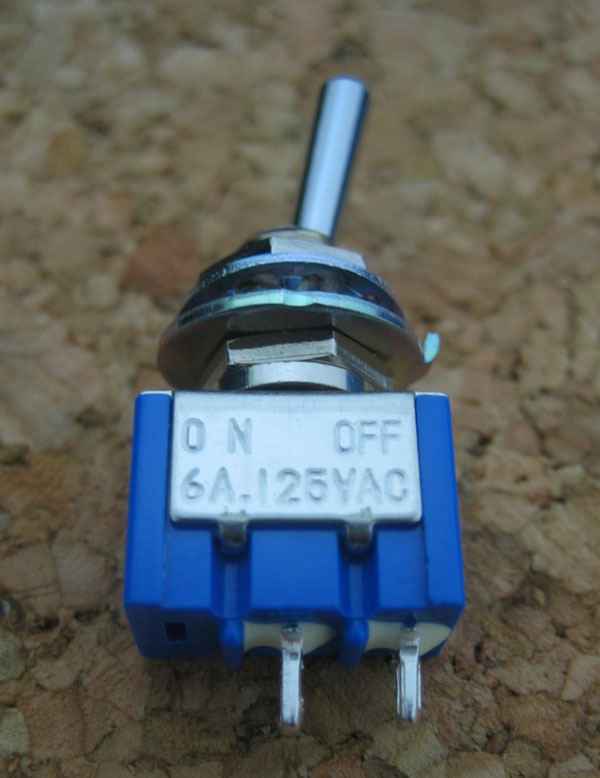 General toggle switch. If there are many legs, it is complicated to know which leg is connected to which leg, so a two-legged one was used. | #5 Heat sink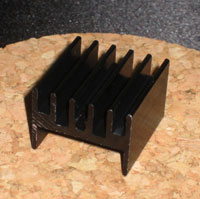 I heard that the TA2020-20 doesn’t generate much heat, but I’ll leave it on just in case. It’s kind of cool. | #6 Bracket LED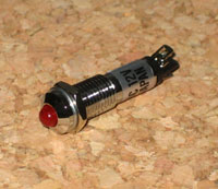 Blanket LED for 12V with resistor, purchased so that it would light up to indicate that the power is on. I regret a little now that I should have chosen green one. |
#7 Knob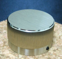 Gold-finished aluminum knob. It seems to have a small scratch and was purchased at an outlet price. The screw that holds the shaft can be adjusted with a 1.5 mm Allen wrench. | #8 RCA plugs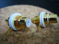 I’m kind of happy with the gold plating. I went with the cheapest one I could find.” It was labeled “high quality” so it must be ok. | #9 Speaker terminals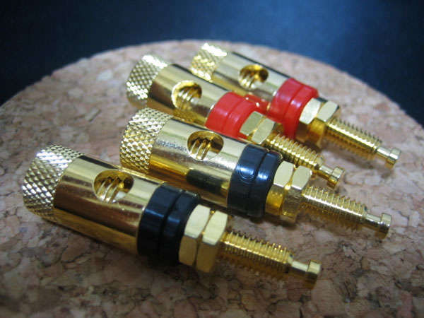 I decided on something cool and gilded. It cost a little more because I focused on the appearance. |
#10 Wiring cable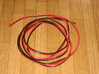 It’s a 30-core parallel wire speaker cable. It will be used for wiring between each terminal and the amplifier. | #11 Ferrite core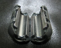 I bought it with the aim of removing high-frequency noise by attaching it to the second stage of a smoothing capacitor. | #12 Case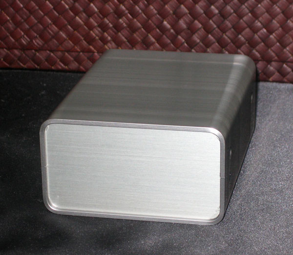 Passport size of W9cm, H5cm, D12cm. This small size is made possible by the external power supply. This case looks very cool. |
Mounting of amplifier part
The amplifier circuitry was mostly as per the Tripath’s data sheet.
http://www.kafka.elektroda.eu/pdf/tripath/TA2020.pdf (Tripath’s data sheet)
The only changes are that the Output Capacitor capacitance is now 0.33μF for 6Ω speakers, and MUTE and SLEEP are dropped to GND.
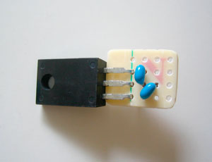
At first, I put the parts on the base.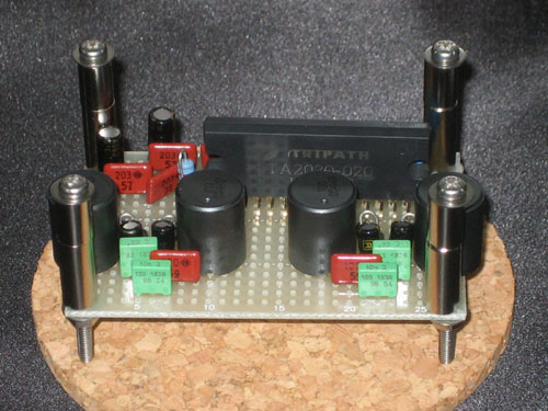
I was able to put all the components on the board just barely sized.
The size of the base was a little small, but OK.
The TA2020-20 IC would not fit into the universal board as is.
Therefore, the odd-numbered legs were carefully bent with pliers so that they would stick into the board.
It took about three hours to wire and solder.
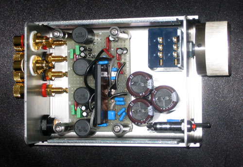
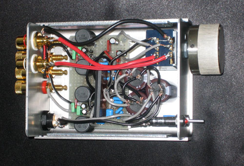
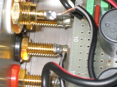
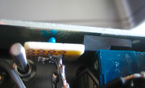
front view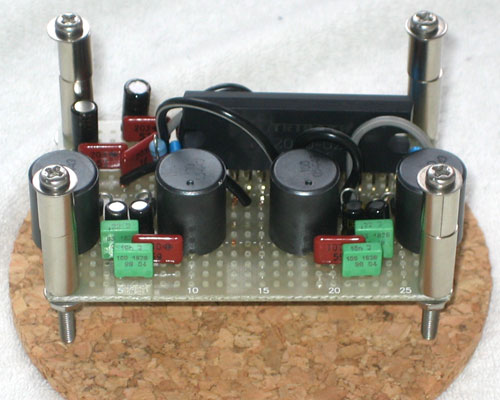
back view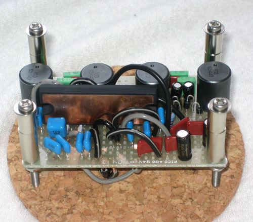
side view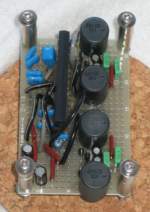
back view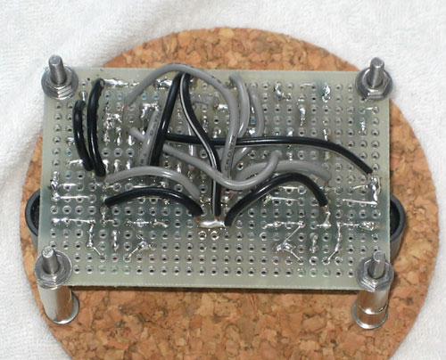
The wiring is a mess.
The IC has 32 pins and is densely packed, making wiring difficult.
It was a mistake to use a small base.
It is very difficult to solder because the components are densely packed.
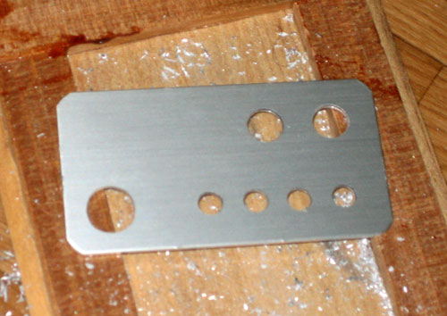
Case processing
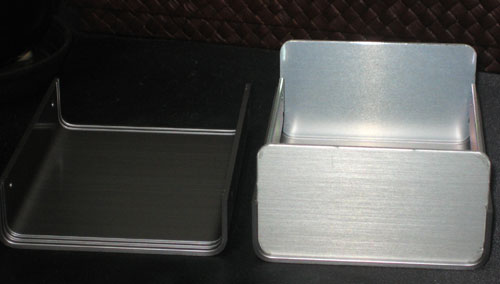
At first, I made a case out of wood, but I failed to varnish it, and I could not deny that it looked like an elementary school student’s free research, so I decided to make a cool aluminum case.
This is the first time for me to process aluminum.
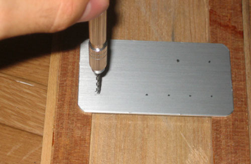
I marked the holes with a pencil and drilled them with a bin vise.
The bin vise is a TAMIYA one that I bought for removing meat from mini 4WD cars a long time ago.
I never thought it would be useful in such a place.
Even if you don’t have an electric drill, a bin vice is enough. (It is hard to drill a lot of holes, but…)
It is surprisingly easy to make holes.
If you make a scratch with a screwdriver or something on the spot marked with a pencil, the tip of the drill will not shift, so it is easy to drill a hole.
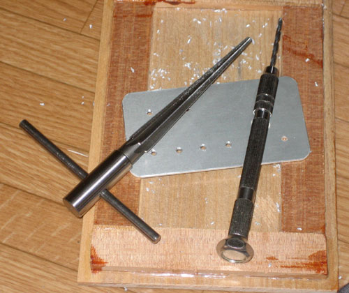
Once the necessary holes were made, the next step was to widen the holes to accommodate each terminal.
So, I bought a “chassis reamer” at a home improvement center. (The reamer is on the left in the photo above.)
It cost about 1,000 yen.
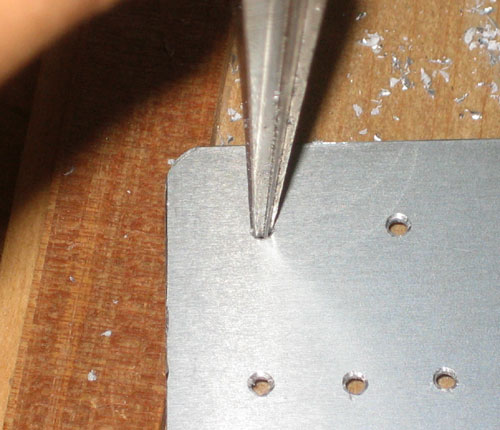
I used a chassis reamer to widen the gouged hole.
It took only about two minutes to widen one hole to the required size.
The remaining burrs were removed by sanding.
The size of the hole for the power supply DC jack exceeded the allowable range of the chassis reamer, so I widened the hole as much as I could with the reamer and then sanded the hole.
The processing of the case was completed.
It took about two hours to complete.
Aluminum is softer than expected, and the processing was quite easy.
Next, the shaft of the variable resistance mini-detent was too long, so it was cut with a hacksaw.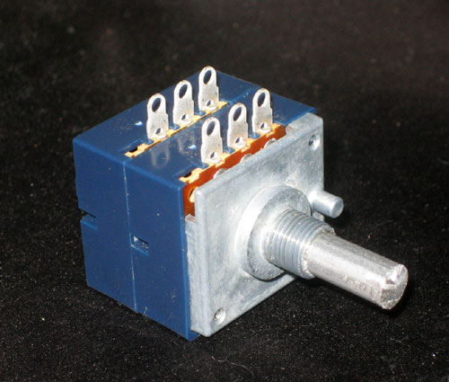
This shaft is also aluminum, so it was easy to cut.
For some reason, my girlfriend had a hacksaw, so I borrowed it.
(I wonder what on earth she is cutting…)
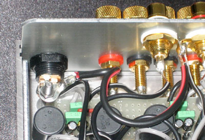
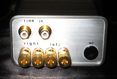
Incorporation into case, wiring
I placed the parts on the case.
It fits perfectly.
The heat sinks and ferrite cores were not installed due to space limitations.
The actual wiring and soldering were completed.
When the case is closed, it looks like this.
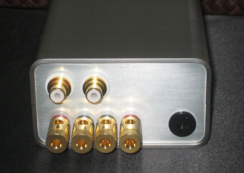
The gold-plated speaker terminals are a nice touch.
Now, will it produce sound?
If not, it is just an expensive box.
This is not the time to talk about bass.
I connected the speakers, sound card, and power supply, and turned on the switch.
The LED blanket glowed red!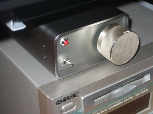
But it doesn’t say “yes” or “no”.
It’s just a box…
Was it a mistake to get carried away and build it on a universal board?
I decided to check the wiring again.
The wiring is messed up and it is very troublesome to check the wiring.
As a result of the painstaking check, I realized that I had not connected pin 2, pin 8, and pin 30, which supply 5V.
I rushed to correct it.
I tried again, excited that this time it would be better.
Turned on the switch!
It didn’t say “yes” or “no.” Again…
Again…
Now, with the power on, we checked the voltage at each terminal using a tester.
I placed the minus terminal of the tester on AGND and checked the voltage at each terminal and IC leg.
VDD -> 12V, so OK
VDD5V -> about 5V, so OK
INPUT -> about 3V (I am not sure if it is right or wrong)
OUTPUT -> about 7V (I am not sure if it is right or wrong)
DGND -> about 3V… this is NG!
I thought that if there is a 3V difference between AGND and DGND, it might not amplify correctly, so I decided to connect AGND and DGND.
Za, za, za -> A music sounded!
At last, the sound was heard!
An emotional moment.
Clear and beautiful sounds flow out.
I was so happy to hear the sound.
I almost cried.
It seems that ANGD and DGND have to be connected.
Sound Impressions
My environment for listening to music is poor.
It may be an environment that makes the TA2020-20 IC cry.
foobar2000 (foo_mpg123.dll) or TV
↓
An USB sound card(Sound Blaster Digital Music LX)
↓
An RCA cable 0.5m(AT5A64)
↓
This TA2020 digital amp
↓
A speaker cable0.3m
↓
SONY mini-component (DHC-MD333)2-way speakers
Prior to building this TA2020-20 amplifier, I was using a mini-component (DHC-MD333) that I have known for 9 years as an amplifier.
The comparison and contrast are these two environments.
| high frequency range | The previous hush sound became very clear. Cymbals and other sounds do not sound crunchy, and the sound of bells is cool and beautiful. The female vocalist’s voice sounds a little dry. It became clearer and much more powerful. |
| middle frequency range | The vocalist’s voice seems to stick out in the foreground compared to the rest of the sound. |
| bass range | I had the highest expectations for bass, and the bass is strong as expected. The sound of drums is realistic and good. It is powerful. |
| all range | I feel clearer. I can now distinguish the sound of each instrument. I wonder if this is what they mean by high resolution. I had thought that digital amplifiers sounded plain, but it has more flavor than I had expected. The thickness of the sound is neither thin nor thick. |
Subsequent modifications
Changing volume position
The volume control is a bit difficult to work with.
Even when the volume is turned down, the sound is too loud, and fine tuning of the small volume does not work. So I changed the position of the volume.
It had been connected in series with the input resistor, but I decided to remove the 20 kΩ nikkorm, which is the feedback resistor, and put a mini-detent resistor here. If I put a VR in the feedback section, the gain would go to infinity when a galliom occurs, which is dangerous, but by connecting the mini-detent’s terminal (3) to terminal (2), the gain will be at most 1/2 even if a galliom occurs.
(Galliom refers to a phenomenon in which the resistance of the VR becomes infinite due to poor contact.) It is said that putting a mini-detent in series with the input resistor will make the sound muddy, but this wiring method eliminates that concern. In fact, the sound seems a little clearer.
Using crimp terminals for wiring to speaker output terminals
Since solder did not easily stick to the gold plating on the speaker terminals, I had been using screws to connect the copper wires between them, but I felt a little uncomfortable, so I decided to try using crimp terminals for mental health reasons.
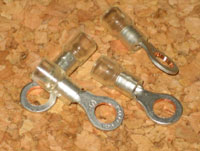
It was $0.5 for a lot like this.
I would have preferred gold-plated ones, but the gold-plated ones were too expensive at $6 and I couldn’t afford them, so I decided to stick with these.
Is this silver plating? I can’t help but feel that it is solder plated.
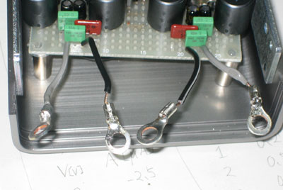
This is how it turned out. I bought the wrong thing and the crimp terminal holes did not fit in the speaker output terminals, so once again the chassis reamers came into play and widened the holes. This changed the sound very much.
The female vocalist’s voice, which had sounded dry, became more colorful and the bass sounded more powerful.
Instead, the cymbals and other instruments became a little crisper, and the overall volume became lower and more hush-hush and cheesy. Personally, I preferred it before the change.
Seems like it would be better to solder directly to the speaker terminals instead of using crimp terminals.
So…
Soldering directly to speaker terminals
This one has much higher volume and resolution than the crimp terminal.
Highs sound very clean.
Female vocalists’ voices also sounded clearer.
However, I am sad that I cannot use the crimp terminals I bought.
Trying to drop GND into the case
I heard that the more solid the GND is, the more bass is produced.
I heard that it is better to put a big nail in the yard and use it as a ground, but we live in an apartment, so there is no way to put a nail in the balcony.
So, I decided to drop the GND into the case, aiming for a slight improvement.
The volume is also attached to the case, so by dropping the case to GND, the volume case can also be dropped to GND.
This will be effective for noise suppression.
I put a crimp terminal across the screw that holds the universal board to the case so that the GND will pass from the screw to the case. I feel that the bass has become a bit more throbbing.
However, there are many contact resistances before reaching the case, so I don’t think it will be of much effective…
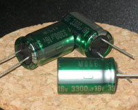
Changed power smoothing capacitors to MUSE FX 3300 micro F/16V x 3
It was time to say goodbye to the cheapest KMG 3300μF.
The sound was not bad, but for my own satisfaction, I had to switch players.
I found MUSE FX 3300μF/16V on a auction for $1.1 per piece, so I bought three of them.
MUSE FX are said to be old and no longer manufactured, but I don’t care if they are a little old or not, Nichicon’s MUSE seems to have a good reputation.
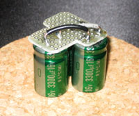
Oops, the wiring is still absurd. However, I was surprised at the change in sound.
– The volume became very loud.
– The sound became thicker and deeper, and the flavor increased.
– I feel that the voice of the vocalist has come to the forefront.
I am glad that the volume has become louder and the taste has increased.
Most of the electric charge sent to the TA2020-20 seems to be stored once in this smoothing capacitor and sent from there, so it seems that the smoothing capacitor has a great impact on the sound.
Amplifier adjustment due to speaker change
The time has come to say goodbye to the mini-component that has been with me for many years.
I completed my own bass reflex speaker using FOSTEX’s 12cm speaker unit FE-127E.
Accordingly, the impedance of this speaker is 8Ω, so the four output capacitors were changed from BG-PK 0.33μF (6Ω spec) to BG-PK 0.22μF (8Ω specification).

The speakers and amplifier are both of my own making, and I am very satisfied with this environment.
Since the amplifier and speakers are the only ones in the world, the sound they produce is unique.
It is a very luxurious feeling to listen to music with this in mind.
DC Offset Adjustment
I get a popping POP noise when the amp is powered up or when the PC is powered up.
I found an offset adjustment circuit on page 11 of the TA2024C datasheet, so I decided to try this on the TA2020.
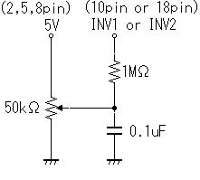
A 5 kΩ multi-turn potentiometer was used as the variable resistor for fine tuning.
Normally, a potentiometer of about 50 kΩ is easier to adjust.
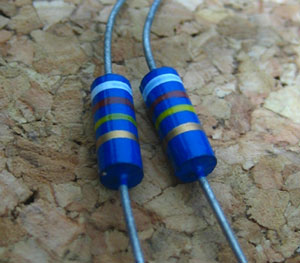
Riken’s Rikenorm is famous for its audio resistors.
They have a colored and energetic sound.
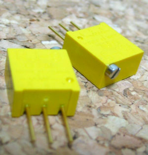
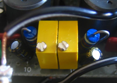
Potentiometer with bright yellow color.
It’s BlackGate, the bass that’s always been there for us.
I assembled the TA2024C as per the schematic.
Even though I changed the value of potentiometer and inserted a resistor
Left: +70mV
Right: -6mV
I could not make it closer to 0 than +70mV.
Since the Left DC offset is 70mV, of course the POP noise was not removed.
I think the DC offset should be adjustable on the TA2020…
It should be possible to adjust the voltage by dividing +5V with a resistor.
It was halfway due to lack of power, and was abandoned without a dare.
Later addition:
I did not connect the input INPUT terminal to GND and adjust the DC OFFSET.
I connected IN1 and IN2 to GND properly and adjusted the offset, and was able to set both left and right to almost 0mV.
This is a relief.
However, I still get a small POP noise when the power is turned on and off.
It is smaller than before, but…
I wonder if the POP noise is caused by the DC offset.
However, when the DC OFFSET can be set to 0, the sound is very good.
The resolution and power are increased.
It is a little bit troublesome, but I can say that there is no way not to adjust DC OFFSET.
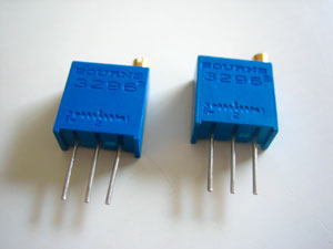
The yellow potentiometer had a small value of 5kΩ, so I changed it to a 50kΩ one.
I found a BOURNS 3296W for $0.7 / piece, so I chose this one. If anyone has successfully adjusted the DC offset and eliminated the POP noise, please let me know.
Relay circuit for POP noise rejection
Even with the DC offset set near 0V, the POP noise could not be removed.
It seems that the POP noise is caused by the transient state when the power supply is turned on and off.
Therefore, I decided to connect the amplifier output to the speaker after the power supply voltage was stabilized to some extent by the delay relay.
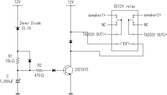
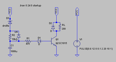
It is a delayed relay circuit that uses transistor switching.
When the amplifier is switched on, the relay turns on in 4.2 seconds,
When the amplifier is switched off, the relay turns off when the voltage drops below approximately 10V. The delay time t was calculated as follows.
Time constant: C x (R1+R2) = 1000uF * 10470ohm = 10.47s
When the voltage between B and E reaches around 0.6V, the transistor turns on and the relay turns on.
Since 10.1V is dropped by the zener diode, a voltage of 12V – 10.1V = 1.9V is applied to R1, R2 and Tr.
0.6V is equivalent to 31% of this 1.9V.
Read the time it takes for the voltage to reach 31% from Charge and Time Constant in “CR Circuit Response (Time Domain Part 1)”.
In my case, the voltage reaches 31% at around 0.4 times the time constant, I obtained the following.
t = 10.47 * 0.4 = 4.188s
In fact, it took approximately 4 seconds from the time the switch was turned on until the relay turned on, so this calculation does not seem to be wrong, although I am not sure.
(Please point out any errors.)
But beware.
How to determine R1.
The relay coil is rated to deliver 41.7mA (for the 12V DC relay I purchased), so I designed it to deliver approximately 60mA to the collector with room to spare.
R1 = (12V-0.6V-10.1V) / (60mA/300) = 6.5[kΩ].
2SC1815 is GR grade, so 200-400, and also R1>=R2. 0.6V is the B-E voltage.
However, I did not have a resistor of about 5 kΩ on hand, so I decided to use a 10 kΩ resistor that I had on hand.
With 10kΩ, it was doubtful whether it could supply enough current to turn on the relay.
I tried to do it one way or the other.
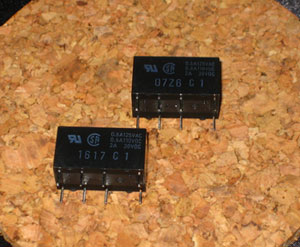
2-circuit 2-contact relay G5V-2 DC12V
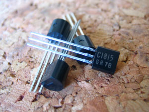
2SC1815 GR
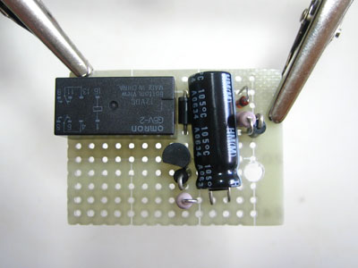
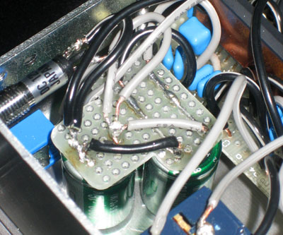
This is what it looks like when soldered to a universal board.
Result
POP sound at power-on has almost disappeared <- Great success
When the power is turned off, a POP sound is heard and then the relay is cut off.
This will counteract the POP sound when the power is turned on.
I set R1 to 10kΩ and was relieved to find that the relay works properly.
However, when the power is OFF, the POP sound is heard about 0.5 seconds after it is turned OFF, which is not a good countermeasure because it takes about 2 seconds for the relay to turn OFF.
It looks like I can shorten the time it takes to turn OFF by moving the zener diode closer to 11.4V, but I don’t know if I can shorten it to 0.5 seconds.
This is because it takes longer for the power supply voltage to drop due to the larger smoothing capacitor in the amplifier than the time constant of this relay circuit.
To eliminate the POP sound when the power is turned off as well, another relay that responds immediately to the power switch would have to be assembled. After that, I simulated the circuit with the circuit simulator “LTspice/SWitcherCAD III”.
It is strange to simulate the circuit after it is finished, but I don’t care anymore.
I could not find a zener diode SPICE model with 10.1V, so I used 9V.
Other than that, I used the same values as in the actual circuit I built.
The supply voltage Vcc is,
0 – 0.1s: 0.6V to 12V
0.1 – 20s: 12V constant
20 – 22s: 12V → 0.6V
0.6V was set as the initial state because the capacitance of the smoothing capacitor is not completely removed even after the power is turned off, leaving a residual voltage of about 0.6V.
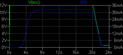
The relay is turned on in almost 4 seconds.
However, I(RL) flows only about 33mA. It seems that 10kΩ is too large.
I should have used LTspice to determine the values of 1000uF and 10kΩ in advance to obtain the appropriate delay time and current value.
5V voltage stabilization
The 12V supply voltage has been properly addressed with smoothing capacitors to prevent ripple and noise.
The TA2020-20 has a regulator inside the IC, and the 5V output from the regulator comes from pin 30.
Pin 2 and Pin 8 receive this 5V.
Pin 2: V5D (digital 5V input)
Pin 8: A5D (analog 5V input) This 5V supplies power supply voltage to various parts.
This 5V must not waver.
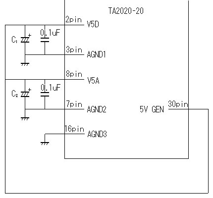
Insert decoupling capacitors C1 and C2 between Pin 2 and Pin 3 and Pin 8 and Pin 7, as shown in the figure above.
It seems that an audio grade capacitor with a value of several hundred μF is good.
It seems that a larger capacitance can be inserted. This decoupling capacitor can suppress the fluctuation of 5V generated by the 5V GEN.
The 0.1μF capacitor in parallel is installed to absorb high-frequency noise emitted from the IC.
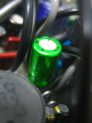
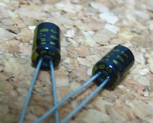
This is the capacitor we chose for C1.
22uF Nichicon MUSE ES 16V UES1C220MEM
I would have preferred a capacitor with a little more capacitance, but I had no choice because this was the only audio capacitor I had on hand.
This is a non-polarized type of MUSE.
I like the sound of MUSE, so even if the capacitance is small, it will have some effect.
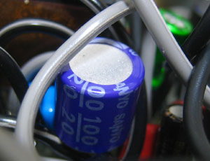
Capacitor selected for C2.
100uF SANYO OS-CON 20V 20SA100
OS-CON is a well-known capacitor.
It is a popular capacitor that shows wonderful characteristics that are hard to believe it is an electrolytic capacitor.
I chose this capacitor for the simple reason that the TA2020-20 would be lonely without an OS-CON.
I heard that OS-CON is suitable for decoupling.
Change in sound
I was amazed at the power of the bass.
This modification is very effective.
The sound has become more spacious, as if the capacity of the low-frequency range has increased dramatically.
This is wonderful.
After that …
5V supply by external switching regulator
I had one 5V switching regulator left over in good condition, so I decided to supply 5V not from the TA2020-20 IC, but from an external source.
I bought a 5V 1A TA4805S for $1.
A 0.1uF laminated ceramic capacitor for high-frequency noise rejection is placed between each pin.
This output is supplied to pins 2 and 8 instead of the 30-pin VGEN of the TA2020-20.
Since there was no longer space for a heat sink for the regulator, the case was used as a heat sink.
Since the TA4805S is a molded package, the package is insulated, so it is safe.
I attached it to the case with double-sided tape.
The wires are already just barely wired.
With such a large heat sink, it will be cool no matter how much heat is generated.
The output of the regulator is smoothed with 3300uF MUSE FineGold.
Sound change by regulator
It got so good that it made me laugh.
The contours became clearer and the resolution increased, as if switching from cassette tape to CD.
It seems that external supply is better than using the regulator inside the TA2020’s IC.
Lettering
It was hard to tell which switch was on or off, so I decided to add lettering.
I got a lettering sheet for about $2 and rubbed the corresponding letters on it.
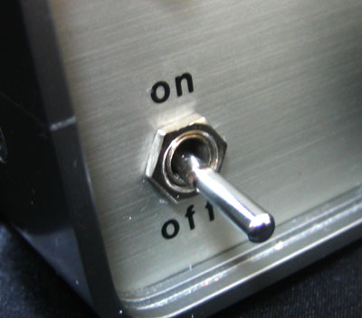
It’s very easy, just press and rub. It was finished as if it were a commercial product. (I noticed that the input of the AC adapter (I think) is “dc”, not “ac”, until I took a picture.
Is it completed?
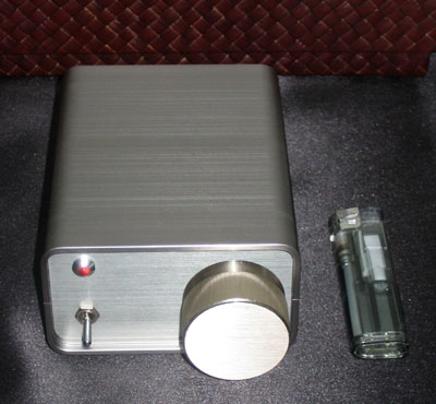
Compared to a lighter, it looks like this.
It is surprisingly small.
It is hard to believe that it is a 20W+20W power amplifier.
Even at this size, it produces a sound that is more than satisfactory, and it could be built at a cost of only $100.
It is an amazing cost/performance ratio and space performance.
Incidentally, this IC is said to be as good as a 100,000 yen amplifier.
Also, it seems that the TA2020KIT can be used to make this IC even more easily without going to the trouble of making it on a universal circuit board.
However, I think it is cheaper to build it on a universal board, and I would be more attached to it.
Now, I am very satisfied with my audio environment by connecting it to this self-made bass reflex speaker.
I hope this page will be of interest to you.
I hope you will be interested in this product,
| More people building amps. ↓ More people buy electronic components ↓ The market for electronic components flourishes ↓ New components are released one after another, and each component becomes cheaper ↓ I can purchase parts at low prices |
The reason is that the arrow “I’m going to go down” will go down and down and down.
What selfishness.
Comments